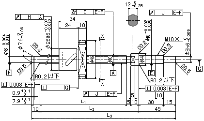
| Ball Screw model No.
|
Stroke
|
Screw-shaft length
|
Screw-shaft
longitudinal-axis
runout
D
|
Nut
circumferential
runout
H
|
Flange
perpen-
dicularity
I
|
Shaft
thread
runout
J
|
| L1 |
L2 |
L3 |
| BNK 1004-2.5RRG0 + 180LC3Y |
50 |
110 |
125 |
180 |
0.020 |
0.009 |
0.008 |
0.008 |
| BNK 1004-2.5RRG0 + 180LC5Y |
0.035 |
0.012 |
0.010 |
0.011 |
| BNK 1004-2.5RRG2 + 180LC7Y |
0.040 |
0.020 |
0.014 |
0.014 |
| BNK 1004-2.5RRG0 + 230LC3Y |
100 |
160 |
175 |
230 |
0.030 |
0.009 |
0.008 |
0.008 |
| BNK 1004-2.5RRG0 + 230LC5Y |
0.040 |
0.012 |
0.010 |
0.011 |
| BNK 1004-2.5RRG2 + 230LC7Y |
0.055 |
0.020 |
0.014 |
0.014 |
| BNK 1004-2.5RRG0 + 280LC3Y |
150 |
210 |
225 |
280 |
0.030 |
0.009 |
0.008 |
0.008 |
| BNK 1004-2.5RRG0 + 280LC5Y |
0.040 |
0.012 |
0.010 |
0.011 |
| BNK 1004-2.5RRG2 + 280LC7Y |
0.055 |
0.020 |
0.014 |
0.014 |
| BNK 1004-2.5RRG0 + 330LC3Y |
200 |
260 |
275 |
330 |
0.040 |
0.009 |
0.008 |
0.008 |
| BNK 1004-2.5RRG0 + 330LC5Y |
0.050 |
0.012 |
0.010 |
0.011 |
| BNK 1004-2.5RRG2 + 330LC7Y |
0.065 |
0.020 |
0.014 |
0.014 |
| BNK 1004-2.5RRG0 + 380LC3Y |
250 |
310 |
325 |
380 |
0.040 |
0.009 |
0.008 |
0.008 |
| BNK 1004-2.5RRG0 + 380LC5Y |
0.050 |
0.012 |
0.010 |
0.011 |
| BNK 1004-2.5RRG2 + 380LC7Y |
0.065 |
0.020 |
0.014 |
0.014 |